Large radius and small arc is an eternal measurement problem. What method is most accurate to measure has become an equation with no solution for millennia in the industry. Today, we will study the following questions to see if there is really no solution.
1. What is called a large radius and small arc?
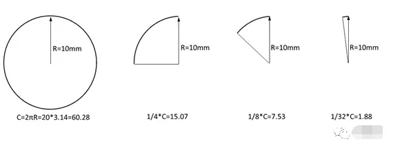
As shown in the figure above, when the arc length is less than 1/4 of the circumference C, we collectively refer to it as a large radius small arc. When the arc length is much smaller than the radius, for example, the arc length is equal to 1/32 of the circumference, the small arc must be measured Determine the radius R, this measurement process will produce a huge radius deviation.
2. How much uncertainty is in the measurement of large radius and small arc?
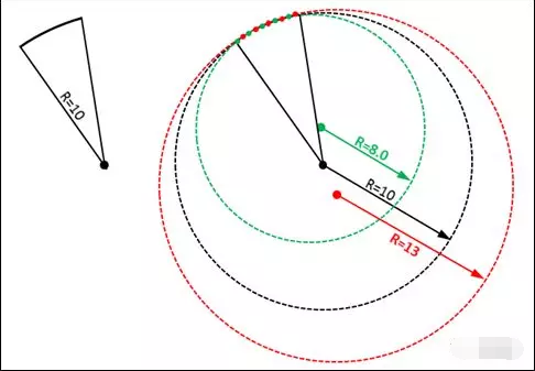
As shown in the figure above, to detect an arc with only 15° and a radius of R10, use OMM to measure 5 points to construct the arc output radius. At this time, only one point position is misaligned between the red point and the green point, but the test result is Great deviation.
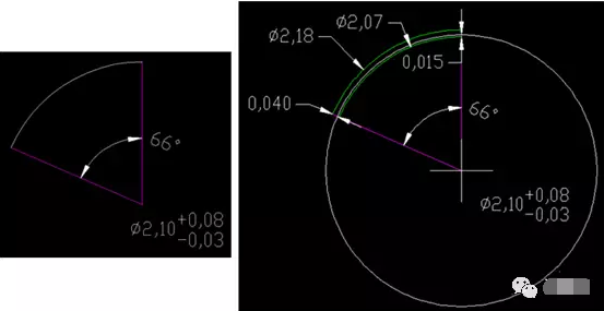
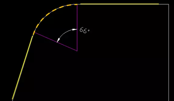
Let us give another practical case. Assuming that the arc angle less than 1/4 of the circumference (<90°) is 66°, the theoretical diameter is 2.10+0.08/-0.03.
The first state:
Assume that the center of the circle has no offset. The upper limit 2.18 and the lower limit 2.07 are respectively marked through the theoretical circle center. At this time, the positive deviation of the radius of the arc is 0.04, and the negative deviation is -0.015. In other words, assuming that the center of the circle does not deviate in actual measurement, the measurement tolerance zone can fluctuate within the range of 0.04+0.015=0.055. This deviation can be fully satisfied by the equipment in theory.
The second state:
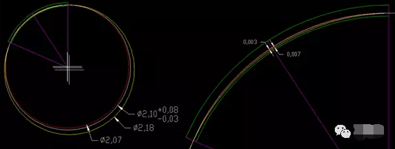
However, in actual measurement activities, the center of the circle will definitely be deviated. By making the angle bisector, assuming that there is no deviation at both ends of the arc, the radius deviation on the angle average line is the largest at this time. In this way, 2.18 and 2.07 circles are made respectively through the two ends of the arc, and we find that passing through the angle average line The positive deviation of is 0.003, and the negative deviation is -0.007.
This shows that if the circle changes within the range of 2.10+0.08/-0.03 and there is no change at both ends of the arc, the maximum deviation allowed on the angular average line can only be controlled within the range of +0.003/-0.007, and In actual measurement, the points at both ends of the arc, the points on the angular average line, and the points on any other positions of the arc will change to varying degrees. We assume that these points are all within the range of 0.005+0.005/-0.005, although This variation is very close to the limit accuracy of the measuring equipment, but the arc formed by all the variation points must have a large deviation.
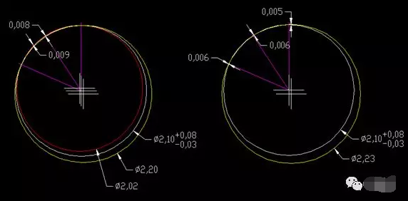
As shown in the above figure, all test points are within μ level deviation, but the diameter of the circle has exceeded +/-0.05, which fully shows that the measurement of large radius and small arc is inaccurate. It is not a problem with the measuring equipment, but the large radius is small. The characteristics of the arc limit it is not qualified for accurate measurement.
Similar to the measurement of large radius and small arc, the most ideal tolerance setting method should be based on the actual assembly requirements of the part, and convert it to the line profile with reference.
For example, in the above case, assuming that the actual assembly requirement is that the allowable deviation of each point of the arc is +0.04/-0.015, then the tolerance accumulation of the reference datum is excluded, and the line profile degree is 0.055U0.04, which is relative to the device μ level The variation of this kind of tolerance can be accurately controlled.
3. Why are these arcs required to be controlled in current design drawings?
Because for special-shaped parts, under the market demand of higher and higher assembly tolerance matching requirements, the cooperation between arcs and arcs is very frequent. Design drawings are inevitable and need to control the arc size, and the current drawing designers design Levels are uneven, especially under the premise of a lack of understanding of GD&T, designers tend to visualize the idea of dimensioning, ignoring the actual fit tolerance requirements between parts.
4. At present, what measurement methods can solve the relatively accurate measurement of large radius and small arc?
(1) By referring to the reference coordinate system of the part, offset the points with equal intervals and measure at fixed points;
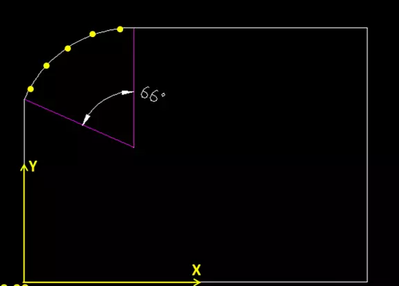
advantage:
It can ensure that each point has a fixed coordinate to ensure the consistency of the measurement;
shortcoming:
When the reference coordinate is unstable, or the vertical and horizontal distance relative to the reference coordinate is relatively large, it will cause the specified point to deviate from the actual range of the arc, or the specified point does not cover 80% of the actual arc of the arc. , This will produce huge deviations.
(2) In the image measuring instrument, refer to the datum coordinate system, translate the datum origin to the theoretical center of the arc, and then switch the rectangular coordinate XYZ to the polar coordinate RθZ, and then take multiple points at any position of the arc and select the radius The worst value deviating from the theoretical radius is regarded as the final measured value;

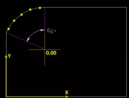
advantage:
Regardless of the accumulation of benchmark deviations, this method can accurately measure the radius deviation of the arc;
shortcoming:
This method requires frequent switching of the coordinate system and manual or semi-automatic picking of points visually, which is inefficient, and is only suitable for engineering development testing and verification, and not suitable for process testing.
(3) If the edges tangent to the arc are all straight edges, you can directly use the intersection of the two straight edges as the origin of the coordinate, and then offset the points with equal intervals to measure at fixed points; while fixing the points, always ensure that all points The X or Y coordinate must not be 0, so as to ensure that the point falls within the arc range to the greatest extent.
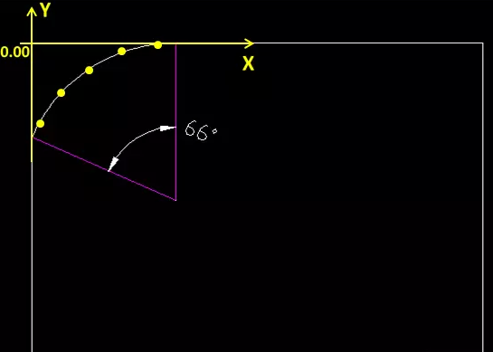
advantage:
This method eliminates the cumulative error of the reference coordinate system and the linear distance tolerance relative to the reference coordinate system.
shortcoming:
When the straightness of the two straight sides connected with the arc is poor, and the ends are deformed, the length of the line directly affects the accurate measurement of the arc.
The solution is to define the starting position of the line through the reference coordinate system, to ensure the consistency of the measured line segment, and to maximize the stability of the test point on the arc.
(4) The tangent arc function is automatically constructed through the straight line and the straight line of the KEYENCE one-key measuring device, and the arc radius is directly read;
Phone: 0769-22265125、22265126/231041125
Fax: 0769-22689102
Service Hotline: 0769-22265126
URL: www.dgzf.com.cn
E-mail: zf@dgzf.com.cn
Address: No. 1, Xiashaling South Road, Xiasha Village, Shipai Town, Dongguan City
Enter the corporate mailbox

Scan and follow